LED VU Meter
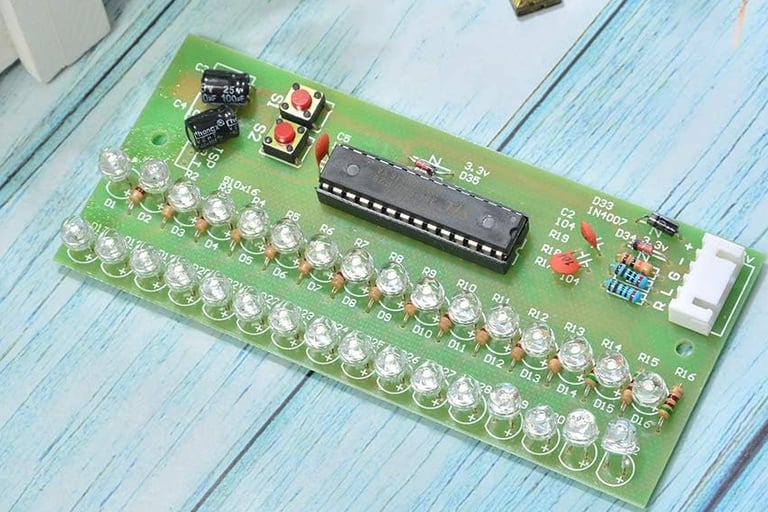
After reading the reviews for the boards available on Amazon, I decided to build my own. This took longer than any other part of this project. All the boards on Amazon had the same problems: cheap round LEDs and weak circuit designs. They all used the TI LM3915 LED bar graph driver, so I studied the datasheet and found a better circuit, adding a precision full-wave average detector. I wanted this meter to work with any amplifier, not just the one I was building, so it needed to solve some problems. In order to use this circuit at speaker levels, it would also need a voltage divider on the inputs. Some amplifiers run in bridged mode, so the negative lead can’t be grounded. This requires differential inputs, so two voltage dividers.
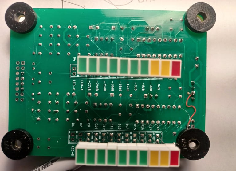
Back View


VU board from Amazon
With an initial design, I ordered some parts and some nice Lumex rectangular LEDs, but I hit a major snag. The LM3915 is out of production, so none of my usual distributors had them. A web search turned up lots of eBay stores that claimed to have them. I really prefer not to buy on eBay, Alibaba, and Amazon for the obvious reason of fake products, but it seemed I had no choice. I bit the bullet and bought 10 units on eBay. I bread boarded up a test circuit and finally had something that was functioning, but when I tested it with a cheap amplifier, it just wasn’t as accurate as it should be. It took a few weeks before I got out a magnifying glass to discover that I had bought LM3915s instead of LM3915s. The difference between the two is that the LM3915 is logarithmic (dB) and the LM3916 is linear. Once I figured this out, my circuit was accurate, just not what I needed, so back to eBay. I ordered 10 LM3915s from another supplier and swapped one in for a LM3916. Same results; it turns out these were not TI but some Chinese brand, and guess what? They must be LM3916s under the paint. I searched again, and much to my surprise, JameCo sells them for 3 times the price, but I can trust them. I ordered 10, and lo and behold, it worked and is very accurate.
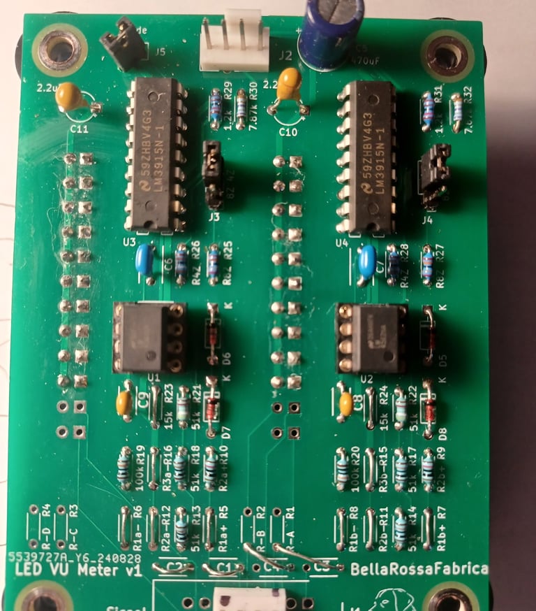
I designed the first revision of the PCB with the flexibility to allow for different types of amplifiers. Therefore there are some unnecessary components that would be removed from later revisions (if there are any). There are 0.1uF input capacitors used with the idea of blocking DC current, but it turned out they are too small and create low-pass filters, so they should be replaced with jumpers. I created a schematic that demonstrates the various input configurations. The input voltage dividers need to be set to keep the voltage into the op-amps below 12V. There are also two feedback resistors, one for 4-ohm loads and one for 8-ohm loads, which set the gain for the precision full-wave average detector. Making these settings will adjust the scale to match the desired power scale.
This module is designed to be installed on an amplifier’s front panel, so most of the connectors and most of the components are installed on one side of the board, and the LEDs are installed on the opposite side. A 3D-printed adapter allows for flush mounting the LEDs and simplifies mounting it to the backside of a panel through a rectangular opening. Pictured is a simple jig made from plywood and 6-32 screws to neatly align the LEDS.


