How I Design And Build a Loudspeaker Page 4
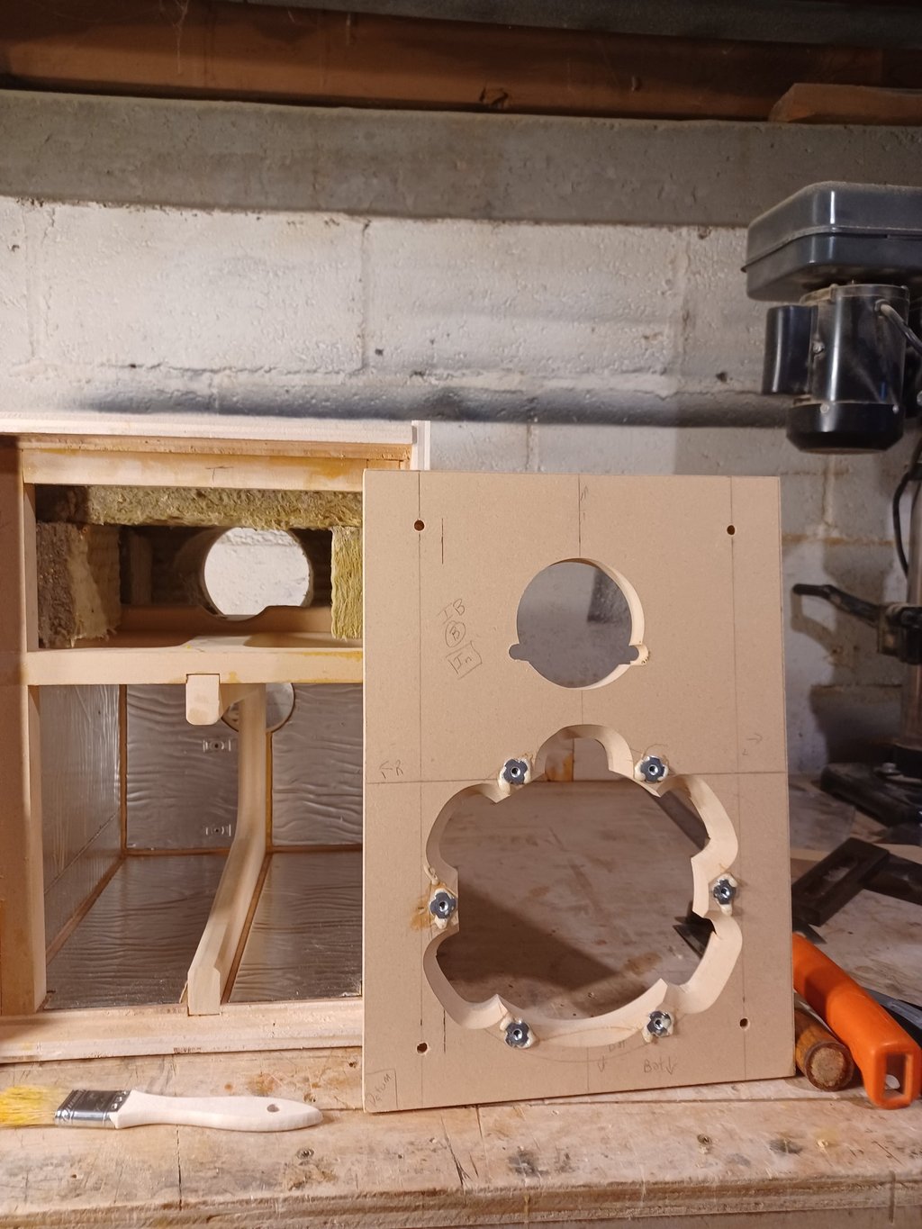
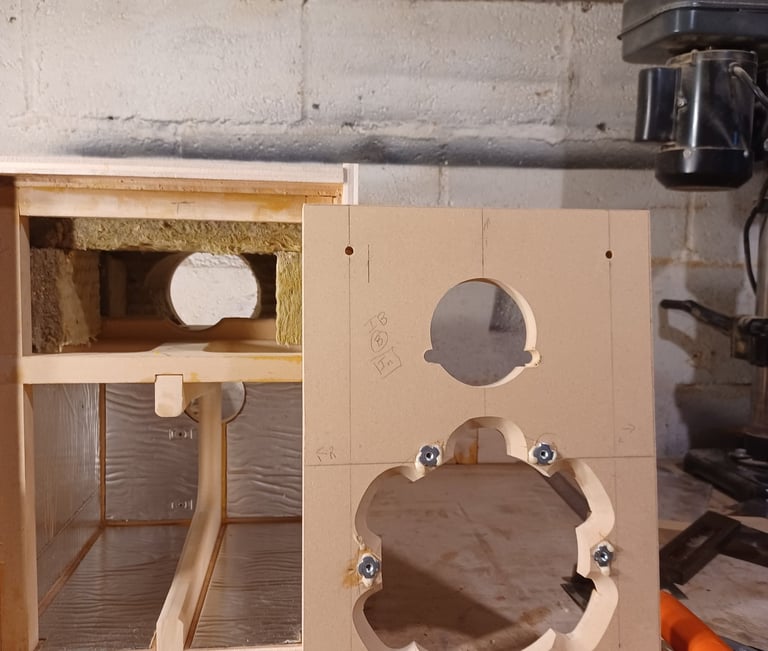
T-Nuts hammered into the mounting holes on the inside of the inner baffle around the scalloping. After losing a T-Nut inside a finished cabinet I now put a few drops of WeldBond glue to secure them.
Before applying the glue it is possible to seal the edges with silicone caulk if you get at the corners. Apply TiteBond II to the rabbets and the exposed ends of the braces and mount the inner baffle making sure the woofer cutout is at the bottom and the T-nuts are on the inside. This is no joke, it happens, just nobody ever admits it. Apply every clamp you own.
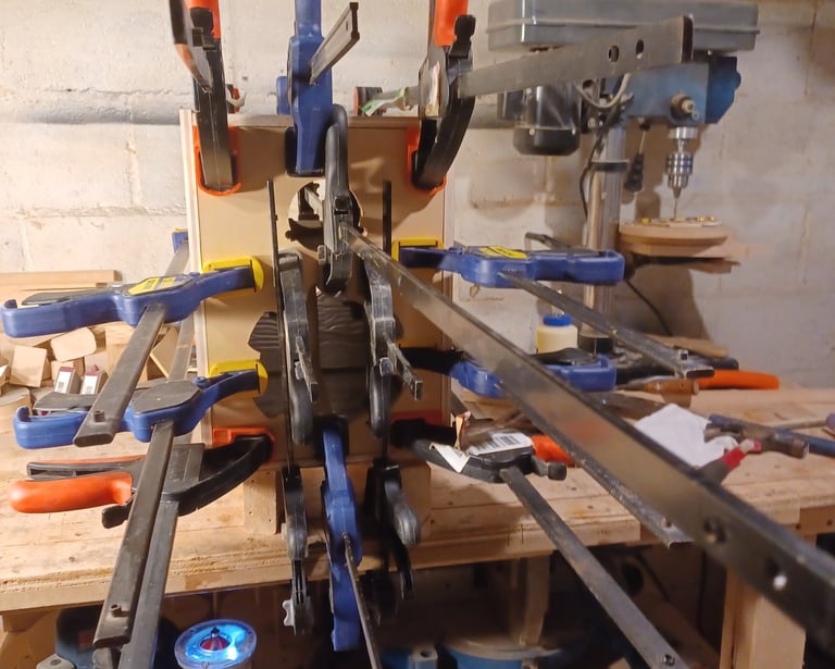
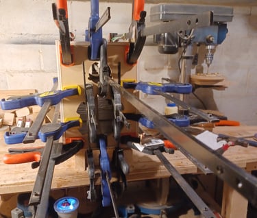
2nd Glue Up - Inner Baffle
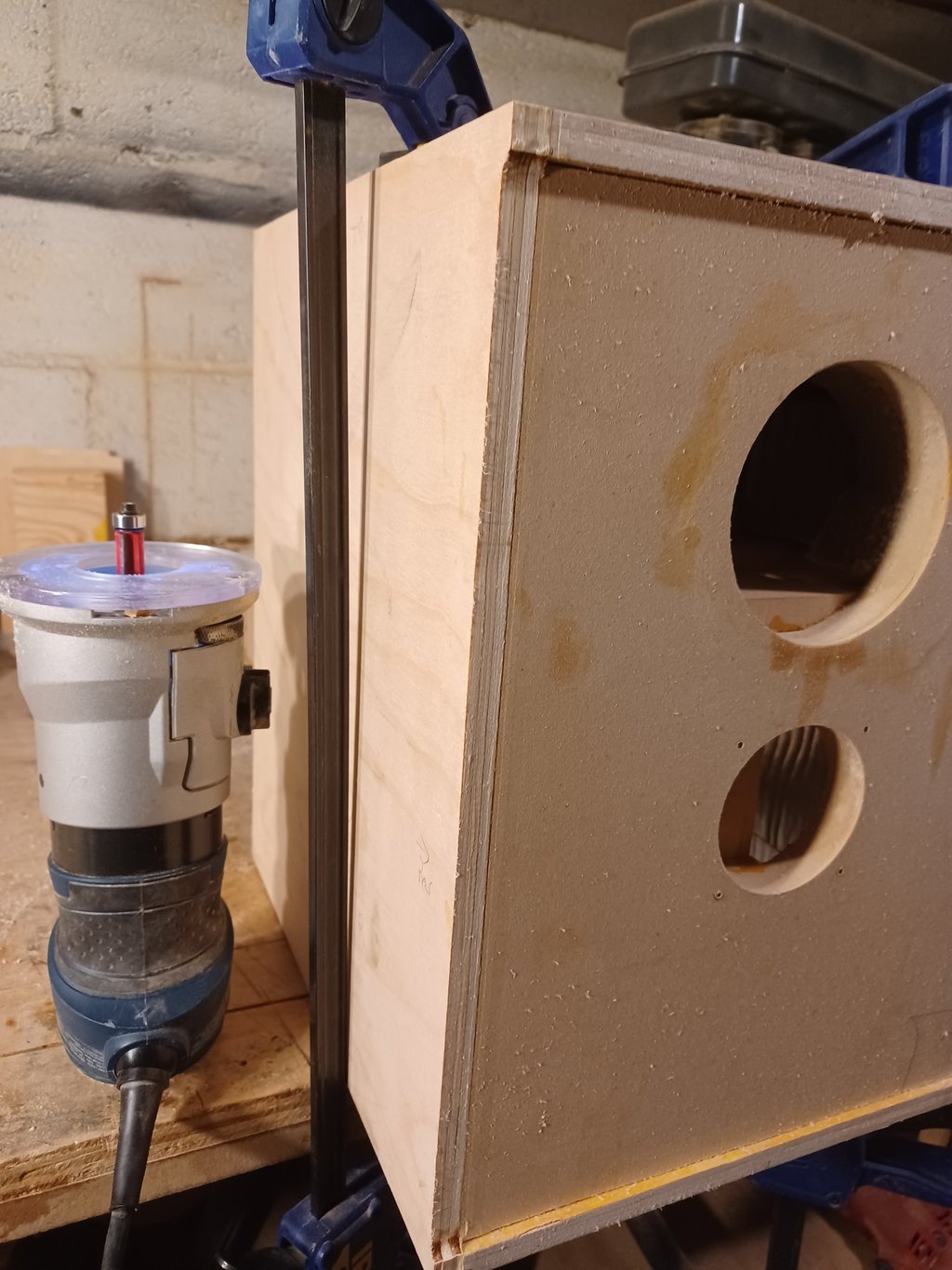
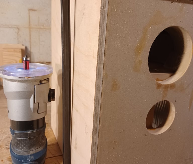
Panel Trimming
Because the panels were cut oversize now use a palm router with bottom bearing trim bit to make the edges perfectly square. Finish with files and sand paper.
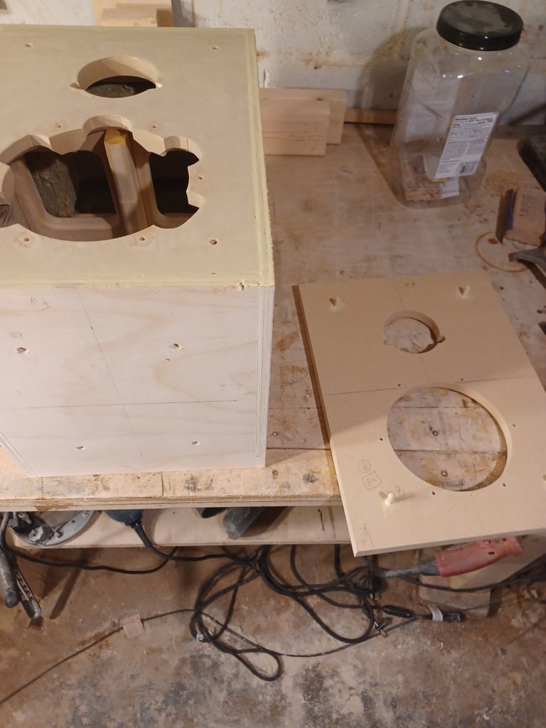
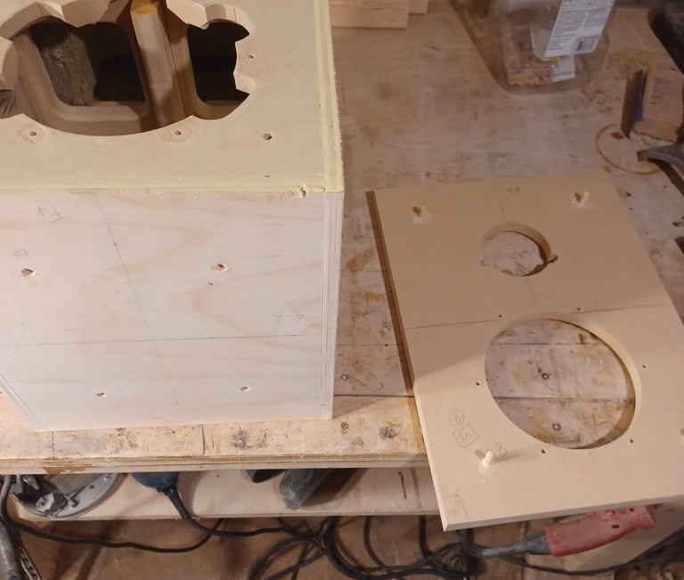
3rd Glue Up- Outer Baffle
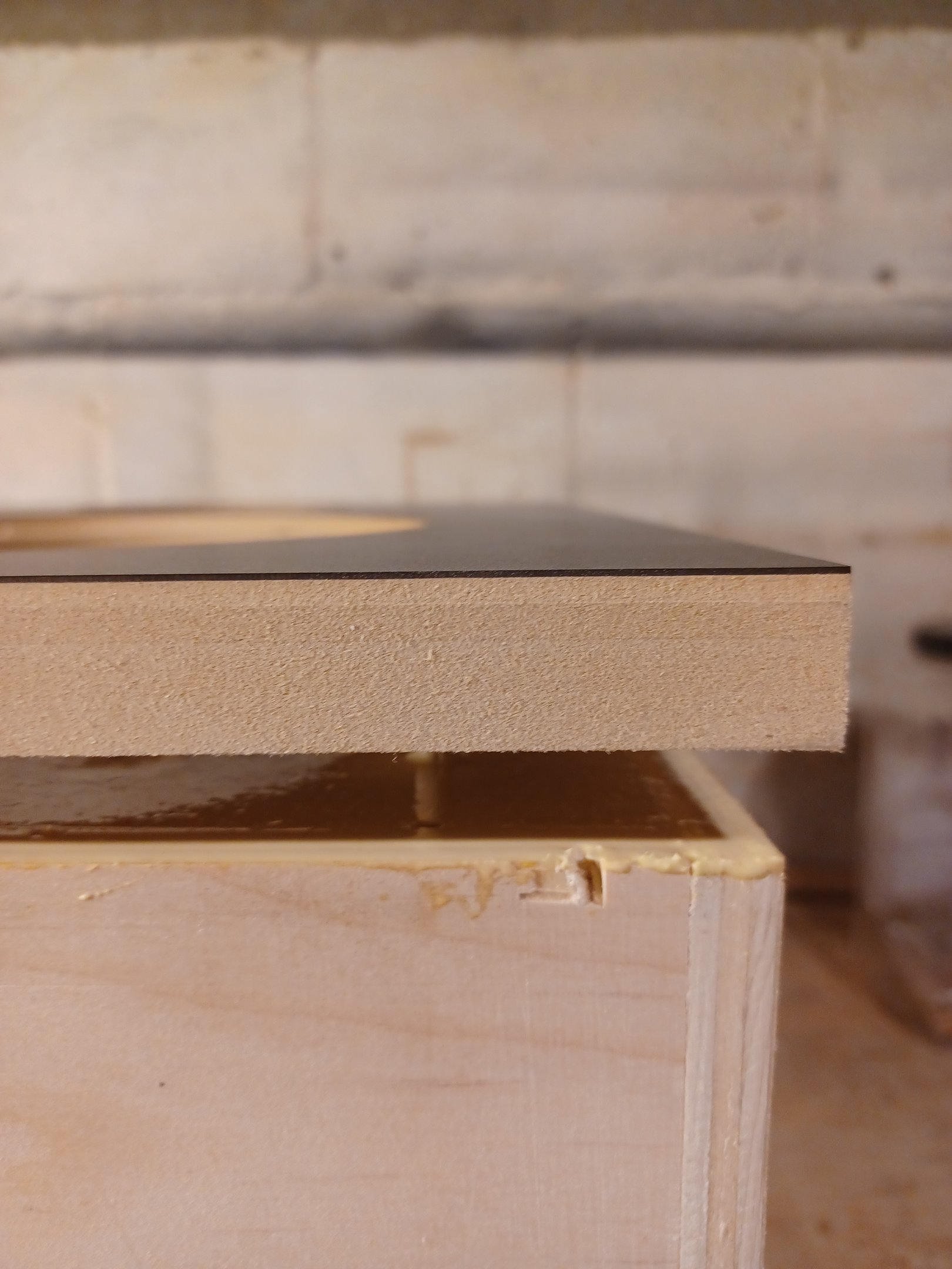
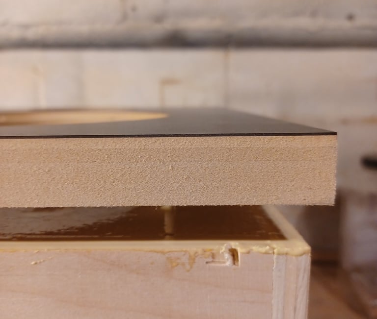
First step is to glue the 1/4 dowel pegs into the inside of the outer baffle. Next spread glue over entire surface of the inner baffle. The photo on the right tries to show the alignment peg. Align the pegs with the holes and push the baffles together then apply all the clamps you own. I use slightly damp Q-tips to make sure no glue gets in the T-Nuts. Once the glue has dried unclamp and use the palm router to trim the MDF square with enclosure.
Crossover Design
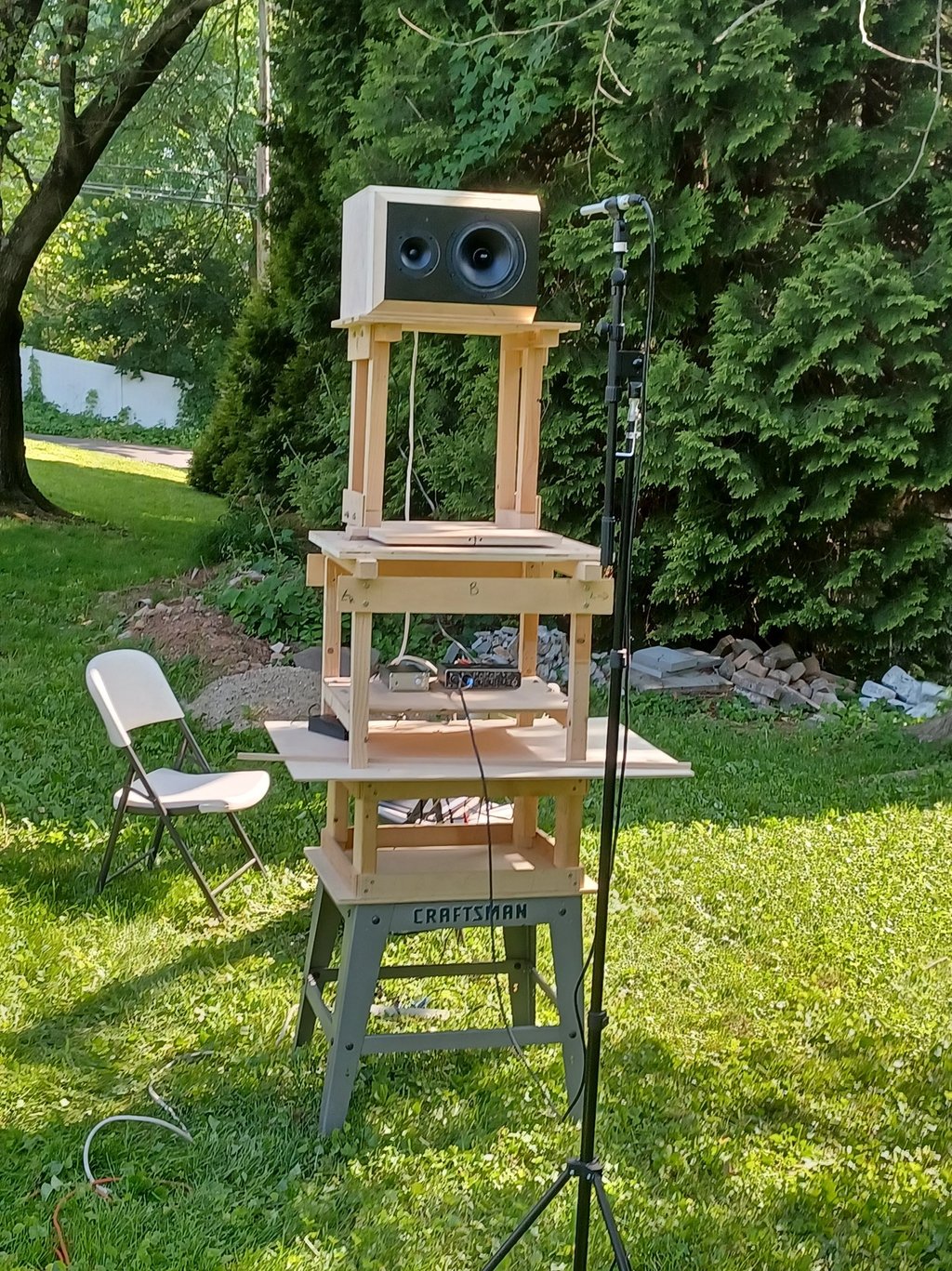
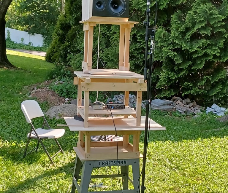
Now that the final enclosure is complete it can be used to make polar measurements and impedance measurements. These will be used to model a crossover. I use the pictured turn table which gets the speaker to a height above the ground of nearly 8 feet. My measurement rig consists of a Behringer UMC204HD USB Audio interface, a SoundID Reference measurement microphone from Sonarworks and REW. I use a Dayton DATS3 for impedance measurements. Then all this data is used in VituixCAD2 to make a crossover design. This is perhaps the longest part of the process. Once I get what I think is a good crossover I will order a single set of components and add other parts to get to the free shipping threshold.
Driver Mounting with T-Nuts