6 Channel Power Amplifier
I decided I wanted to replace the very heavy 8-channel SpeakerCraft BB865 Class A/B 8-channel amplifier I use to drive some active 3-way stand mounts in my office. There were no problems with the existing sound, but the amplifier was causing the shelf it was sitting on to sag a bit. I wanted something lighter, so I made my mind up to build a 6-channel class D amplifier to replace the 8-channel class A/B. I decided to use pre-built class D modules rather than build something from scratch because I never had a talent for trouble-shooting switching power supplies, and class D circuits seemed to me to be similar.
As much as I would have liked to use Purifi or Hypex products, the price was simply too high, so I started looking at the next tier down in OEM products. I had seen more than a few posts on the forums discouraging using IcePower amplifiers, but the prices are more in line with my budget. I saw Amir’s review of the 125ASX2 on ASR and decided to look closer at the IcePower modules. I also had been interested in the CDA modules from ClassD Audio powered by an Antek power supply. There was very little technical data on the CDA modules, so I decided not to consider them and spent a few days poring over the IcePower datasheets and put together this chart.
Front Panel
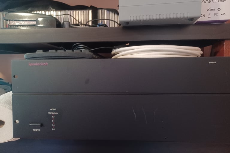

SpeakerCraft BB865
I wanted to match or exceed the 65W per channel of the SpeakerCraft amplifier, so I rejected the 50ASX2 for anything but driving a tweeter. The distortion specifications for the older 100AS2 and 200AS2 modules are on the high side, so I rejected them too. This left the 125ASX2 and the 250ASX2 modules. I spent many hours going back and forth trying to justify price versus distortion specifications and almost decided to use a mix of modules. I went back to the IcePower website and noticed another option that was not available from Parts Express, a modular system for building multichannel amplifiers. The more I stidied the datasheet, the more I started believing this was what I wanted. The woofer and mid-range drivers in my speakers are 4 ohm so 80W output met my power requirements and .03% THD at 6.6kHz matched or bested all the ASX2 modules. Next, I needed a source for the modules. IcePower sells samples directly from their website and also cable kits to make testing easier.
I had started research in late July and had pretty much made up my mind in mid-August after a few emails back and forth with Anders at IcePower. I had a trip planned for mid-October, so I decided to wait until just before I left in October to order the modules. A funny thing happened when I went to place the order; the ICEpower400SM power supply was out of stock, but there was a link to Profusion, a distributor in the UK that had stock. The power supply was about the same price, but the ICEpower80AM2 amplifier modules were substantially cheaper, so I ordered everything but the cable kits from them.
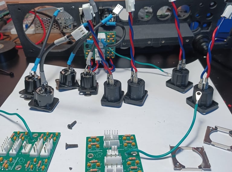
Once I committed to the IceMatch solution, the next step was to design an enclosure to house the modules and the other parts I needed to make a usable amplifier. I am using a DBX DriveRack PA2 for an active crossover, which has balanced outputs, so I planned on using XLR for inputs. My speakers use SpeakOn connectors, so SpeakOn connectors for the amplifier outputs made sense. I had previously designed and built a Raspberry Pi controller to connect a 12V trigger from a preamp to control a relay to power the DriveRack and delay the 12V trigger to a power amp. It also controls 4-wire fans and monitors temperature probes. The device was currently housed in an external box, but I decided to integrate it into the new amplifier enclosure. The ICEpower400SM power supply delivers auxiliary voltages, but my design exceeded the 1A limit on the 5V supply, so I needed to add a second power supply.
Inspired by the retro look from the 70s, I settled on wood for the top and sides of the enclosure. I chose a 12” by 12” piece of ¼ inch aluminum plate for the bottom of the chassis. This created a nice ground plane for all the modules. I don’t have a good way of machining aluminum, so I investigated using Front Panel Express, LLC. The price for just the back panel in ¼ inch aluminum was $164.00, so I didn’t bother to use their software to lay out the front panel. This made me decide to use ¼ inch plywood for all panels. I had some nice ¾ inch quarter-sawn sapelle and some cheap ¼ inch maple plywood to build a frame and panel box. As I started laying out the modules, I realized that 12” by 12” would be a little cramped, so I decided to make a larger bottom panel from plywood and screw the aluminum plate to it.



EMC Boards and Neutrik Connectors
Fully Assembled
Background


Planning
Physical Design
LED VU Meter

Electronic Design
A/C Power
Because of my desire to integrate my Raspberry Pi controller, I required, in addition to an IEC C14 socket, a NEMA 15P outlet and a 5A circuit breaker. I puzzled over mounting these components on ¼ inch plywood for quite some time before deciding to use a plastic Bud box and mount it to the back panel. I didn’t want to splice cables to make wiring harnesses, so I used a screw terminal strip block to interconnect all the A/C cables instead. Finally, I added a 5A relay module. To save money, I cut up 14 AWG power cords for cables and soldered spades for terminations to the terminal strip. I used ring terminals, toothed washers, and 6-32 screws for earth grounds to the aluminum plate.
Inspired by the retro look from the 70s, I settled on wood for the top and sides of the enclosure. I chose a 12” by 12” piece of ¼ inch aluminum plate for the bottom of the chassis. This created a nice ground plane for all the modules. I don’t have a good way of machining aluminum, so I investigated using Front Panel Express, LLC. The price for just the back panel in ¼ inch aluminum was $164.00, so I didn’t bother to use their software to lay out the front panel. This made me decide to use ¼ inch plywood for all panels. I had some nice ¾ inch quarter-sawn sapelle and some cheap ¼ inch maple plywood to build a frame and panel box. As I started laying out the modules, I realized that 12” by 12” would be a little cramped, so I decided to make a larger bottom panel from plywood and screw the aluminum plate to it.
EMC Board
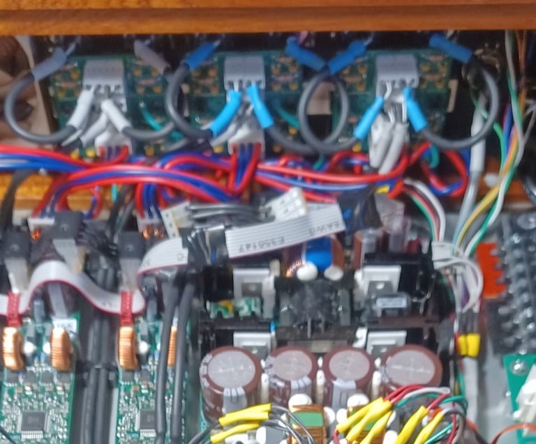
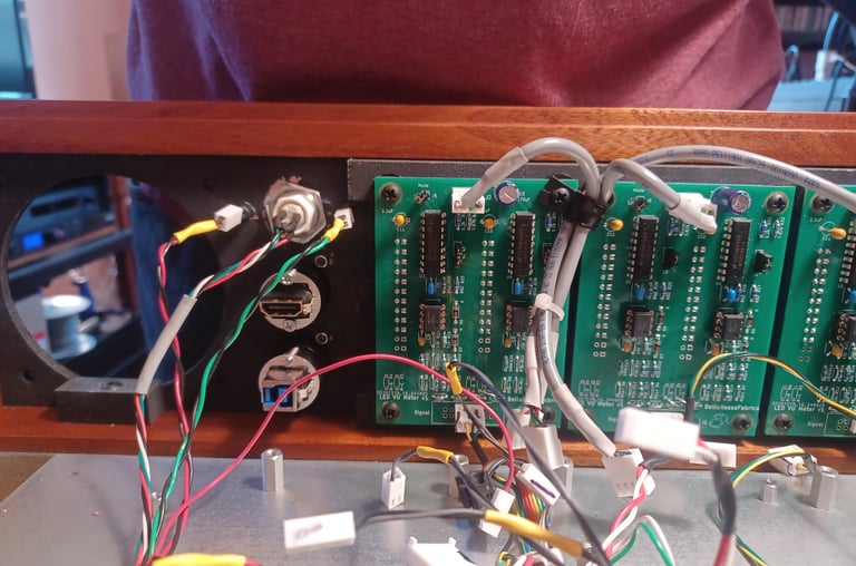
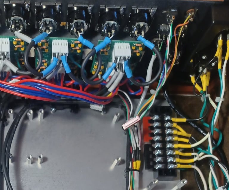
Electromagnetic Compatibility (ECM) is required for both the line-level inputs and the speaker outputs. I designed a PCB for both inputs and outputs to connect to each of the ICEpower80AM2 modules based on the recommendations from the datasheet. They are attached to the back panel to place them as close as possible to the input and output connectors. They are connected to the aluminum plate with ring connectors, star washers, and 6-32 screws. Lastly, I added a 4-pin header to attach VU meters to the speaker outputs.
Amp-Power Board
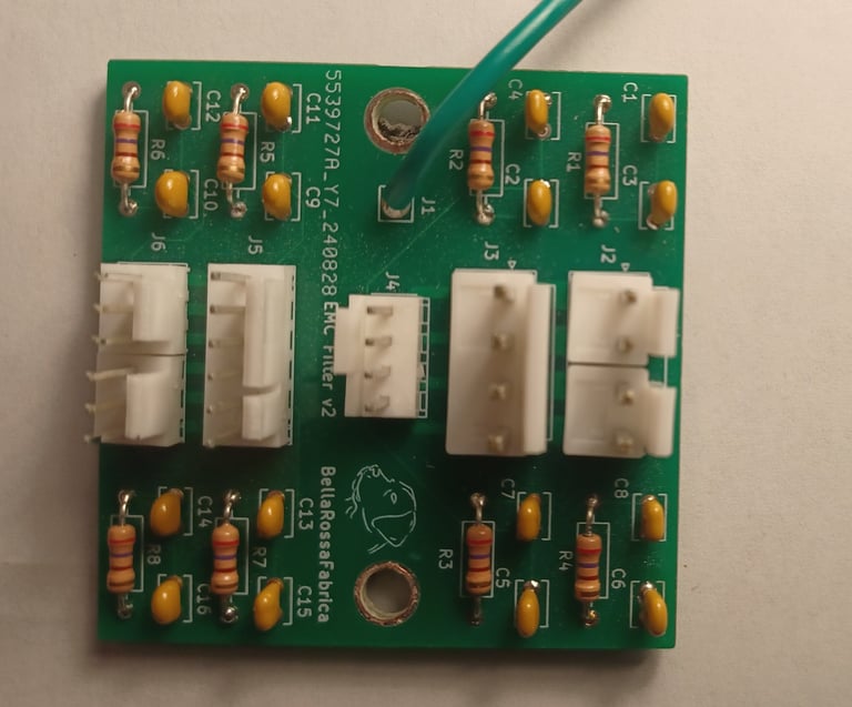
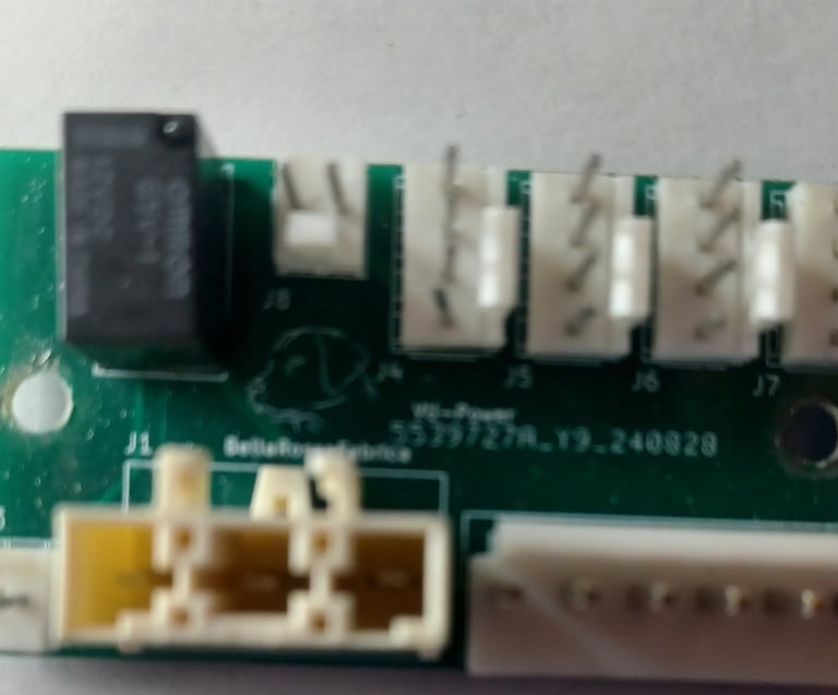
With the desire to avoid splicing wiring harnesses, I designed a D/C power distribution board to connect a switching power supply to all the non IcePower modules. I included a relay and a back panel switch to disable the 5V power to the VU meters mounted to the front panel.
Interface board
While cabling, I ran into many instances where I would need to splice cables that needed to terminate to multiple boards or where a component needed to be front mounted and required a connector small enough to fit through a mounting hole. Because I didn’t want to place another PCB order to JLCPCB, I built the Interface board on a BusBoard with point-to-point wiring.
Cabling
There is an incredible number of cables to connect all this stuff together. There are actually 25 different cable layouts and 44 cables, if I counted correctly. They use 14 AWG for A/C and D/C power connections and a combination of IDC ribbon cable or 22 AWG stranded wire for signal connections. Most wire harnesses are secured by zip ties to cable tie mounts connected to the aluminum base with 6-32 screws.
LED-VU-Meter boards
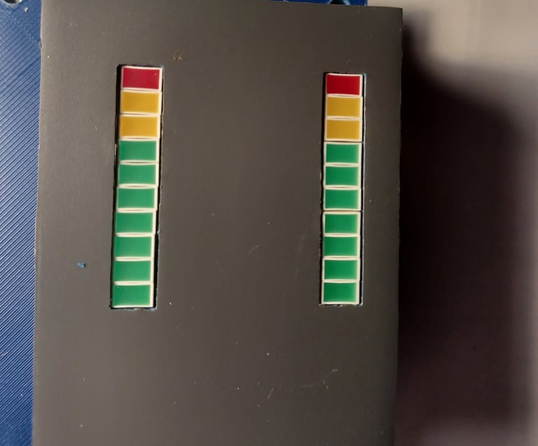
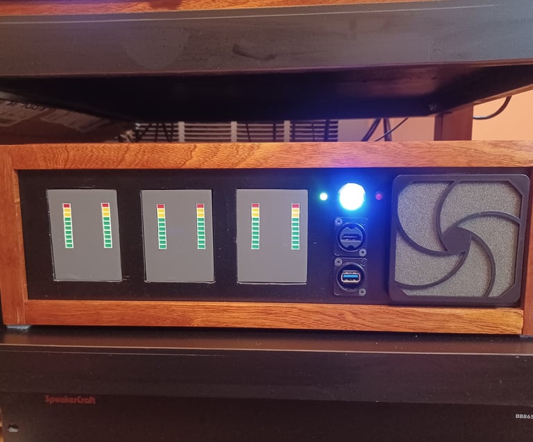
Sticking with the retro theme, I wanted to have VU meters. Adding six analog VU meters would simply require too much real estate on the front panel. I decided to use six LED-based meters. I used Input Variation #6 to match the ICEpower80AM2 monitor requirements. See link to separate page for this module.
5A Relay and A/V Controller boards
See link to separate page for these modules.
A/C Wiring

EMC Board

Power Distribution Board

Cable Harness


IceMatch Features
During the design process, I discovered a few handy features of the IceMatch system and decided to incorporate them in my design.
ICEpower400SM
I used the ICEpower400SM power supply 12V trigger input, which saved additional circuitry for remote triggering. I used the 12V preamplifier supply voltage to signal to my controller that the amplifier is powered on. The ICEpower400SM also has red and green LED outputs that signal standby and active states, respectively, which are connected to LEDs mounted on the front panel. It also has signal sense inputs, but I didn’t use this feature, but I imagine connecting it to one of the bass channels would work to trigger a multichannel amplifier. Even though I’m in the US with 120V A/C I added the bulk capacitor option, which is recommended for A/C supply below 115V. It didn’t cost much, and Anders replied to my question about this with, “Less improvement to be experienced at 115 V. Try it out.”
ICEpower80AM2
The amplifier modules have a few handy features that help simplify my design. I used the monitor outputs, which are single-ended -20 dB outputs, to drive my LED-VU meters. This allowed me to configure the meters with single-ended inputs, which solved grounding complexity, and the -20dB level feature removed the need for voltage dividers. The amplifier modules also have disable inputs, which I connected to the controller to create a muting option. I did not need the BTL feature because I was mostly driving 4-ohm loads, which are not supported in BTL mode.
6c Amp Front

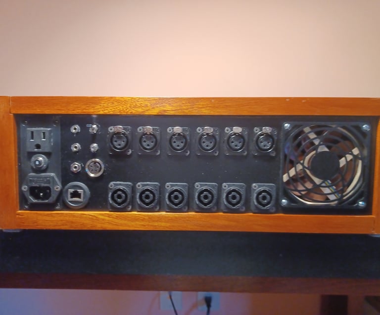

6c Amp Back
Final Thoughts
This is a successful project; it functions well, and there is no audible distortion that I can perceive. I have no facility to make amplifier measurements, so these are purely subjective comments. The total cost of roughly $1200.00 for the project may seem a little high to many, but with the cost of the IceMatch amplifiers and power supply at less than $400.00, the bulk of the cost came from building a complete solution. Obviously, building a 6-channel power amplifier can be cheaper, but I honestly do not see too many places to make substantial savings.
There are some things I would change if I were to start over again. While building, I noticed that the cabling was cramped in a few locations, especially between the aluminum plate and connectors on the back panel. The back panel layout is a little tight. Therefore, I would increase both the depth and width of the case, perhaps 2 inches deeper and an inch wider. It took me a lot of time to make the VU meters accurate, but unfortunately that accuracy makes them no fun. I listen to music at fairly moderate levels, which, in the case of a 3-way speaker, means that very little power is required for each channel. Therefore the lowest-level LED, which represents a mere 3 watts, never lights. If I increase the level beyond my preferred listening level, I am able to drive the base channels up to 3 LEDs, which equates to 6 watts. Because of this I would either adjust the gain on the LED-VU-Meters to make bouncing lights or leave them out completely. Lastly, I believe the solution on using the Bud Box to mount the A/C power connectors would be to use a slightly wider and deeper model because I had to cut too much material to make it work.
